Looking at old maps it is amazing to see how
land and water intertwined once in the northern part of the
Netherlands, Noord Holland and Friesland in particular. It is
even more so, when one drives through Noord Holland and reminds
oneself that this once was a patchwork of islands and shallow
stretches of sea. The Dutch fought - and continue to fight - the
sea and at the same time a good part of the populations lived
off the sea. The Zuiderzee
once was a vast bay of the North Sea, reaching deep into the
country, nearly down to Amsterdam. It served as throughfare for
transport and as a rich fishing resource. However, pressure
on the scarce land was high and the sea was a constant
menace to the low-lying shores and islands. As part of their
struggle against the sea, the Dutch dammed up the bay by a large
dike, the Afsluitdijk,
completed in 1933. This put an end to much of the fisheries. The
already in its southern part brackish Zuidezee finally turned
into a large freshwater lake, the Ijsselmeer.
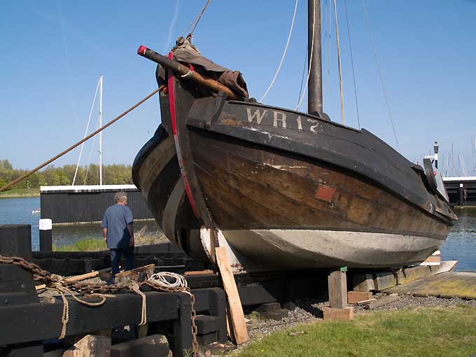
Botter BU130 built 1875 in Spakenburg and registered at
Bunschoten. Now preserved at the
Zuiderzeemuseum, Enkhuizen. Photographed in 2009
Over the course of history there have been
various types of sailing fishing vessels with numerous local
variants. The best-known is probably the Botter (and its larger
variant Kwak). At one stage it was estimated that there were
over 1000 in operation at the end of the 19th century. The
places around the Zuiderzee with the most botters were
Enkhuizen, Volendam/Edam, Monickendam, Marken, Bunschoten and
Urk. Spakenburg was an important building place.
Man's tools to win a lifelihood constantly
change and are being adapted to changing circumstances, new
needs and fashions as well. Thus methods of fishing evolved in
order to increase efficiency and in response to changes to the
fishing grounds and other environmental circumstances that
influenced the availability of the resource 'fish'. The history
of the botter is not easy to trace as no artefacts have survived
and artistic renderings are not so reliable bevore say the late
18th century. As with all small boats, they were built without
any drawings well into the 20th century. The botter or its
somewhat larger version the Kwak as we know it today developed
over the past two hundred years.
Sizes vary, but a typical botter has a keel of about 34 feet long.
Sources
There are quite a
number of comprehensive printed works on the botter and its
history (see below). These include also drawings. Some original
drawings are preserved in various museums in the Netherlands.
However, like so many traditional small boats, botters were
usually built without any drawings. The museums also preserve
various model built from about the early 19th century onward.
There are also surviving quite a number of original botters, the
oldest being from the last quarter of the 19th century.
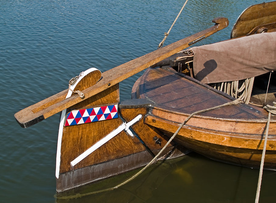
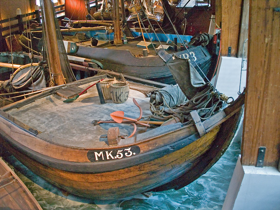
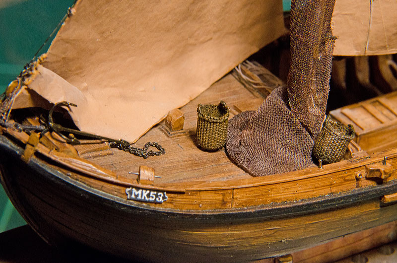
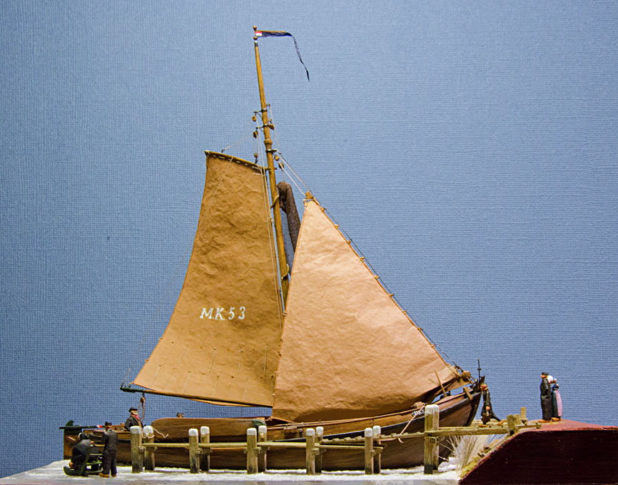
Botter
MK53 (1919) from Marken, preserved in the Zuiderzeemuseum,
Enkhuizen
These boats survived because they have been
adapted as pleasure craft. Obviously a lot of concessions had to
be made in this case to accomodate the modern leisure-boaters
and therefore these boats are not useful for a reconstruction.
In more recent years some of these have been reconverted into a
state that is more like their original workday appearance. Also,
from the end of the 19th century onward some botters had been
built als pleasure craft for private owners. They usually
deviate somewhat from the work boats and are often fitted with a
cabin, as is found e.g. on boeiers.
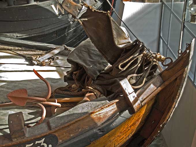
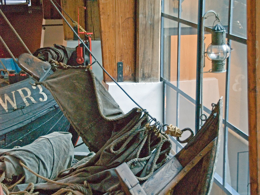
The Zuiderzeemuseum
in Enkhuizen preserves a late botter in its boathall. The Zuiderzeemuseum
also has a large collection of ship- and boatmodels, including
several botters. Some of the models appear to be contemporary,
while others have been built in more recent times.
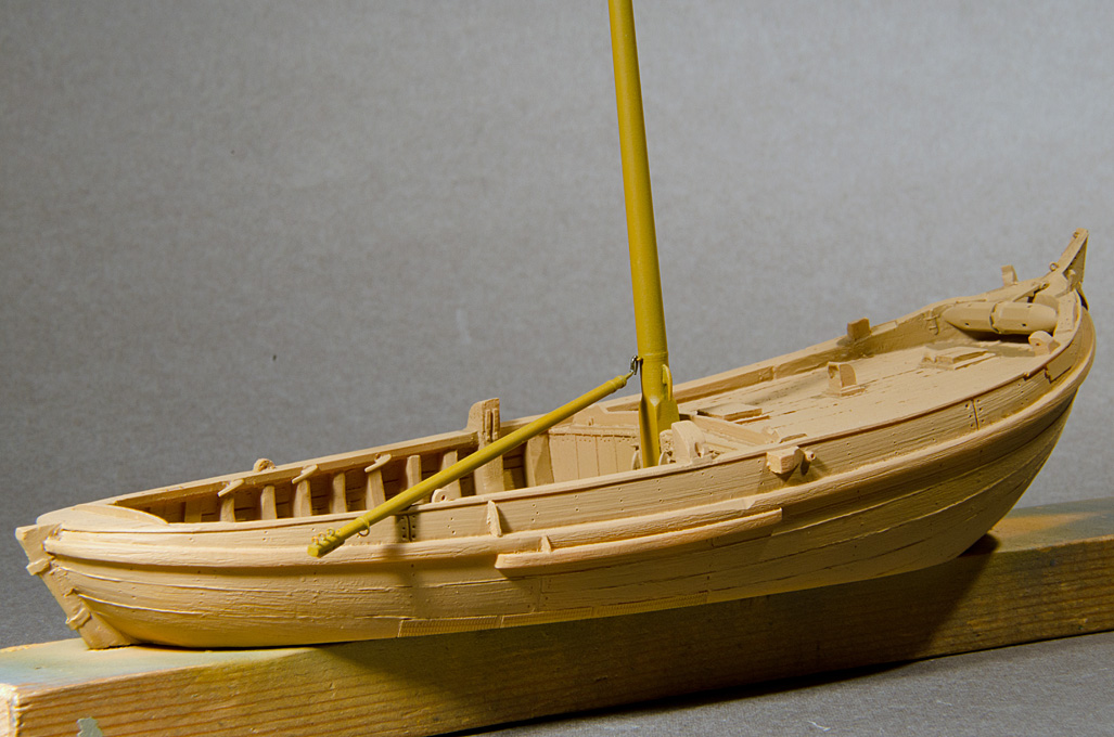
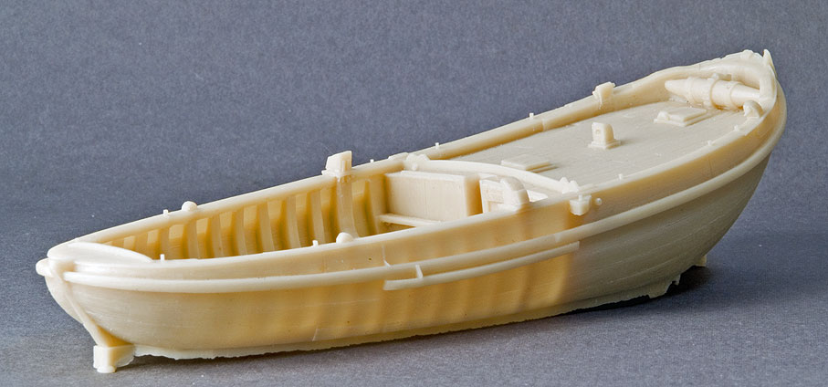
The model is based on the resin kit produced
by Artitec in 1:90 (HO)
scale. This company has developed a real mastery in casting
complex and large resin parts. In addition to the hull, the kit
contains castings for the mast and spars, for rigging blocks
and, somewhat strangely perhaps, the taken-down sails. Of
course, these kits are mainly meant as accessories for model
railway layouts and people not knowing a lot about these craft.
The kit also contains a small fret of etched parts, mainly for
the ironwork of the rigging. While the etched parts are well
made as such, they are for the most part not really useful for
representing the forged ironwork. For instance, masthoops are,
of course, flat in the horizontal direction, while they should
really be short tubes. Other parts simply lack the needed
plasticity. Hence most of the etched parts will not be used.
Similarly, the cast rigging blocks will be replaced by home-made
ones and 'real' sails will be made. I bought the kit 'second
hand' and the at some stage the characteristic high stem head
was broken off and a new one will have to grafted on. Various
other details will be improved for better definition of the
shapes. Although the casting is well made, there are certain
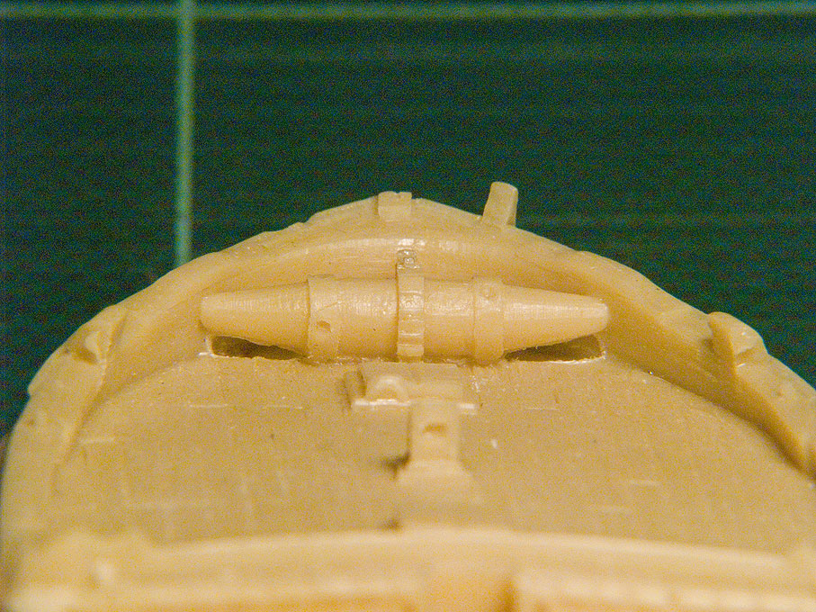
limitations due to the casting process. A company policy of Artitec is to limit the
number of parts and to cast-on as many details as possible. Thus
for instance the spill is cast onto the foredeck. There are
limitations to undercuts in the silicone rubber molds, hence the
barrel is not completely free. I shall have to remove the
material underneath the barrel using a scalpel etc.
The
Artitec
polyurethane resin castings (note that the
stem head is broken off)
Not only are Artitec masters in casting
kits, but also in painting them as is evidenced for instance by
the diorama of the Texel
Roadsted and models in various other museums around the
Netherlands. Below is a finished botter model from their
Web-site.
- 03/10/10
The building began
with removing the casting pips. It appears that the model was cast
upside-down, so that excess resin is found only at the bottom of
the hull. This excess was cut off with an abrasive disk in the
hand-held powerdrill. The bottom was then ground flat onto the
waterline on a piece of wet-and-dry sanding paper. It is important
to hold the hull securely during the various building steps. To
this end two 2.5 mm holes were drilled into the solid part of the
hull and tapped for M3 screws with which it can screwed down on a
piece of wood for safe handling. The tapped holes will also used
to hold down the model in its dioramic setting
The hull casting
was then inspected for any flash and it removed with a scalpell
and files. Luckily, there was hardly any flash. As the next step
the hull casting was compared with drawings from the literature,
mainly BEYLEN (1985) and DORLEIJN
(2001), as well as the above photographic images. As is discussed
below, it will assumed that the model represents a botter from
Marken. Botters from different regions differed in characteristic
details and these should be represented as true as is reasonably
possible at this small scale. When going over the casting a number
of 'problems' were noted: a) the spill lacks some definition of
detail, although the general shape is well represented; also a
pawl bit is modelled, while normally the pawl would be pivoted on
the inside band of the bow; b) the horse for the traveller of the
main sheet is foreseen as an iron bar (an etched part), while the
more common arrangement is a wooden horse integrated into the
slightly raised stern-platform; c) the leeboards are meant to be
glued onto wedge-shaped protrusions on the main bollards; on the
prototype, the leeboards are suspended on a pin that ties into a
band that is laid around the bollard; d) the horizontal wooden
knees left and right of the stem-head are missing, but the whole
stem-head has to be rebuilt anyway. In addition, holes for
thole-pins etc. have to be drilled through. There are other little
bits and pieces that need to improved, but they will not all be
listed here.
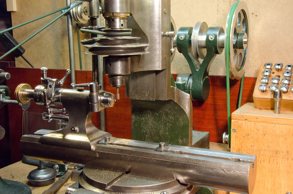
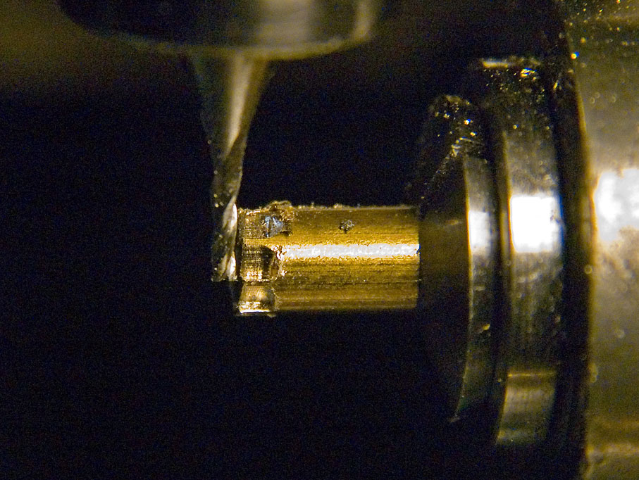
Cutting
the slots for the handle bars of the spill
Milling
the ratchet wheel of the spill on the dividing
attachment
Parting-off the
ratched wheel
The parts assembled
on the spill stem
Free-hand turning of
the spill ends
Milling
the eight sides of the winding drum on the dividing
attachment
The finished spill
drum
The
spill installed
Improved
main sheet horse
Improved
rudder
- 03/11/10
Given the problems
with the spill, it was cut completely from the moulded hull in
order to be rebuilt as a separate item. Square holes and
recessions cannot be easily machined from the solid. Therefore the
spill was built up from a number of parts that would allow
machining, The 0.5 mm x 0.5 mm holes for the handle bars were cut
as slots into a section of 4 mm round brass bar. The ratchet wheel
was cut on the milling machine with a dividing attachment. All
part had a 1 mm hole drilled through to take up a 1 mm brass rod.
Brass was chosen in order to be able to soft-solder all parts
together for the subsequent machining operations and to provide an
axle. The cigar-shape of the spill was turned with the Lorch
free-hand turning device. The piece was then transfered back to
the dividing attachment on the mill and the eight sides of the
winding drum were milled on.
In between, the hull-moulding was freed from
cast-on belaying and other pins as well as the collar for the
leeboards. All parts that will be replaced in metal for better
definition. The respective holes for belaying and thole pins
were opened up properly. The missing stem-head was fashioned
from an off-cut piece of polyurethane resin. Bands and rubbing
strakes for the forestay haliard were added from styrene sheet
and copper wire. On close inspection it was found also that the
stern piece was too narrow to accomodate the pintels for the
rudder. It was widened with a piece of resin stuck on. The
tiller from the kit didn't look quite like what I had seen in
the literature and on real boats. Consequently a new one
was rough millled from a piece of plexiglas and finish filed to
shape. The tiller was completed with the band from styrene that
holds it together. in the prototype.
The horse for the traveller was also
fashioned from a piece of Plexiglas that had just the right
thickness. All seams were filled with putty. From putty were
also sculpted the stem knees. The horse also received rubbing
strakes from thin copper wire.
- 16/03/11
Leeboards
Milling clamps
Slicing-off
clamps
Clamps
installed
Installing caulking
Mast
on the milling machine
The mast in its
ironwork
The leeboards are cast in resin, but due to
the casting process in an open mold, their back is flat and
without any sculpting. In reality, they are not just flat boards,
but they have a cross-section almost like a propeller. In fact
they are hollowed out over some part to create some hydrodynamic
lift that counteracts the leeway and also pushes the leeboard
against the boat. Using files and diamond rotary burrs the
appropriate shape was given and also the separation of the
individual boards of which the leeboards are composed were marked
out.
There are various belaying clamps distributed
around the hull. The kit has photoetched parts for these, but
somehow they appear rather flat. In addition some or all of them
would have to be of the single-horned variety, rather than the
more common double-horned one, as forseen in the kit. Replacements
were milled raw from a strip of brass and sliced off on the lathe.
They were finished using the hand-held power-drill using small
grindstones and polishers.
Again, the casting of the hull is nicely done,
but Artitec were a bit overenthusiastic in depicting a rather worn
state. If there were such big gaps in the hull, the boat would
sink to the bottom of the Zuiderzee like a sieve. To counteract
the rather rustic appearance, fly-tying silk was glued as
'caulking' into the gaps using varnish.
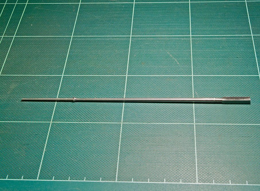
The cast mast was nicely done by Artitec - in
principle, but was too short for a boat of this size, did not have
the right chocs for a boat from Marken and above all was warped. A
new mast was fashioned on the lathe from a piece of steel rod - I
did not have suitable stock of boxwood or similar and brass,
aluminium or plexiglas would have not been stiff enough. The mast
was turned in steps on the watchmakers lathe. This also allowed to
turn-on the mast bands. It was then transferred to the dividing
attachment milling machine to mill on the squares. The
various eyebolt and cranes were fashioned from copperwire and
soldered or glued on.
- 23/08/11
As the mast, the boom was turned on the lathe from a 2 mm steel rod.
The flexing of the rod was utilised to obtain the taper towards both
ends. Again the bands were turned on and the boom was tranfered to
dividing apparatus for drilling the holes for eye bolts etc. The
goose neck was turned from steel and the square, where it attaches
to the boom, milled on using a very small end-mill.
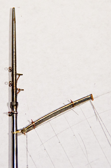
The gaff has a rather odd, pear-shaped
cross-section. In addition its longitudinal shape is rather
crooked. It was fashioned from a piece of brass wire that was
tapered off and bent to the right shape. A piece of brass sheet
was cut to follow the curve of gaff and hard-soldered to the brass
wire. The pear-shape was filled-up with soft solder. Then the
claws that were fashioned from brass were soldered on. Finally,
the 0.2 mm holes for the line with which the sail is attached were
drilled. The gaff was completed with various bands fashioned from
partially flattened copper wire.
Turning
the boom
The gaff, still
without bands on the drawing from VAN BEYLEN's
book
The
completed
gaff
and boom
Mast tabernacle
Boom
end
and thole pins
Iron-work for
leeboard
Guide
for running bowsprit
- 23/02/12
The smithy of the boatyard has been busy and turned out various
pieces of ironwork for rigging and other purposes:
The mast is held in its tabernacle by a latch hinging on
eyebolts.
There is a complex piece of ironwork that guides and holds
down the running bowsprit (which will not be shown on the model,
as it was normally left home during the winter season, when a
reduced rig was used). The ring was turned from a piece of brass
rod, while stay was fashioned from a piece of steel rod on both
the lathe and the mill, as it has partially a square section. In
fact, various parts of the ironwork do have square sections,
inter alia to prevent them from turning, or because they have
made from square bar, hammered to a round cross-section where
needed.
The leeboards are held by sort of square rings that slip over
the leeboard-bollards. These rings were made from brass strips
soldered together and filed to shape. The leeboard pivots on a
bolt that is held by these rings.
A major challenge were the various belaying and thole pins. On
the prototype theyr maximum diameter is just under 40 mm, the
cylindrical sections generally being around 20 mm. So, in the
1/90 scale this means they are 0.2 to 0.4 mm in diameter, with a
length of 3 to 4 mm. There are five different types and the
literature (VAN BEYLEN, 1995; DORLEIJN,
2001) gives the typical dimensions and shapes for each them.
Turning them from the available brass was impossibe, so that 1
mm steel wire was used as starting material. Even then turning
them flying, i.e. supported only in a collet in the headstock
proved impossible. This lead to the design and manufacturing of
a tailstock-held
micro-steady. The spherical parts on the pins where shaped
free-hand using files and abrasive paper strips.
Cross-pin in belaying bollard
Micro-steady
for turning belaying pins and similar
Shaping rigging blocks
on the milling machine with the aid of a diving head
Slotting
the rigging blocks on the lathe
Milling
slots into rigging blocks
Jewelling press with
shop-made anvils
Selection of
blocks before painting
- summer 2012
Though still a long way away some preparations for the rigging
of the model were made by designing and building a miniature
rope-walk.
- autumn 2012
I have been
thinking very hard on ways to make really convincing rigging
blocks of late 19th century model. Some of the blocks would
have to be as small as 1.6 mm long, while the typical block
would be just under 2 mm long. Most of the blocks would have
to have external ironwork. The ropes for the running rigging
typically would have a diameter of somewhere between 0.15 mm
and 0.25 mm in 1/90 scale, depending on the particular rope.
This would mean that quite a large number of holes of
equivalent diameters would have to drilled to a depth of
around 1 mm, which is a bit of a challenge. I wanted to avoid
this by cutting slots into the material and inserting real
sheaves turned from brass. The slots at the bottom would have
to be filled in later. The outside shape of the block was to
be milled in the dividing head from round stock. A table was
prepared that calculated the exact distance of the cutter from
the centre-line for each pass, so that eventually the oval
shape would emerge. This raw part then was transferred to the
lathe for cutting the slots. While perhaps a good idea from a
theoretical point of view, the slotted material proved to be
too flimsy for further manipulation. Therefore, a different
method was devised, for which the material was changed from
brass to Plexiglas. The outside shape was cut as before, but
instead of using a flycutter, a dental burr was used, which
due to its smaller diameter exerts less force on the part.
Then the holes were drilled at pre-calculated positions. The
cross-section of the future blocks were positioned in the
round Plexiglas stock in a way that the axes of the sheave
would coincide with the rotational axis of the dividing head.
This arrangement allowed the sheave to be milled out of the
solid. Many shipmodellers just drill their blocks and perhaps,
if they have a thin enough tool, attempt to file the edges of
the hole round to give an indication of the sheave. However,
this never looks quite right, with the ropes sort of sticking
out sideways from the, rather than running around the sheave.
These blocks then were cut off from the stock on the lathe. It
should be noted that the stock was turned down at the end, so
that it could be inserted into the collets against a shoulder,
ensuring repeatable positioning. The latter was needed, as the
dividing head on the lathe and the one on the mill use
different types of collets.
The botter has a variety of rather
special blocks that also needed to be made, such as the
sheepshead-block for the foresail. They were produced the
technique described above, but in some instances were
'eyeballed' from the stock in the dividing head. One
violin-block was also built up from hard paper with real brass
sheaves and filed to shape by hand. The blocks were completed
with 'ironwork' from copper wire. On the prototype this
ironwork is forged from different sizes of bars. The
blacksmith shapes the cross-sections as needed either flat
(around the shell of the blocks) or round/oval for the hooks.
This process was repeated up to a point by flattening the
round copper wire used. In order to flatten the wire in a
controllable and repeatable way another watch-repairing tool
was adapted: a so-called jewelling press. This tool has a
piston the movement of which is controlled by micrometer stop.
I made some anvils and pistons for it that allow to squeeze
the copper wire to a preset thickness over a particular
length. The thickness is set with the help of a feeler-gauge.
- January/February 2013
Drawing sail plan 'as built'
Panels
of sail-'cloth'
Assembling the sail from the
panels and adding doublings etc.
Fake
eyesplices
Completed
sails ready to be painted
With many parts of the boat actually
completed, I turned my attention to the sails. I did this before
painting the model, as various fitting and shaping actions will be
required that may damage the paintwork.
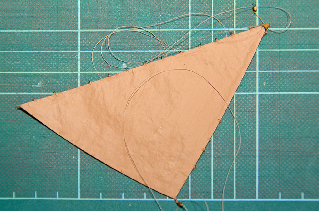
The plan is to show the sails in a sort of
semi-set stage, as they would be when the boat is in harbour in
order to allow them to dry. This going to be a much bigger
challenge to represent convincingly than fully set or furled
sails. As the boat will be shown in its winter rig, there will be
only two sails.
The raw material is a very thin tissue paper
that I found in my stock. The first step was to draw a sail plan
'as built', i.e. with the actual dimensions of the mast, boom and
gaff. The shape of each panel of sail-cloth was pencilled in also
with the help of a french curve. The drawing then was backed with
a piece of stiff cardboard and covered in clingfilm. Based on this
pattern the individual sail-'cloths' were cut from the tissue
paper with the addition of 1 mm for the seam. This is rather wide
at this scale, but inconsequential as the sail will not be
translucent, being tanned and dressed (i.e. soaked in a broth from
bark and smeared with a concoction of tallow, oil and ochre) on
the prototype. This treatment prevents the formation of mildew and
allows to furl the sails when wet. Using the drawing as a
template, panels were stuck together using wood-filler (CLOU
Schnellschleifgrundierung) as glue. The tissue paper soaks
up the filler, turning it into a sort of compound material. I
prefer wood-filler over diluted PVA-glue because it does not swell
the glue and the joints can be loosened and re-adjusted by
applying a drop of thinner. After completing the basic sails,
outside margins and doublings were added in the same way based on
the detail drawings in VAN BEYLEN,
(1995) and DORLEIJN (2001).
The next thing to go on was the bolt-rope. The
rope was made on the miniature
rope-walkfrom 8/0 size tan fly-tying yarn
(UNI-Thread). According to the authors cited, is was left to the
individual sailmaker whether the bolt-rope was sewn to the port or
starboard side of the sail. I attached all doublings to the port
side and decided on the starboard side for the bolt-rope. Again it
was glued on using the wood-filler. On the prototype the bolt-rope
does not continue all-around the sails, but rather ends at the
respective head in spliced eyes. The mainsail is attached to
corresponding eyebolts in the gaff with hooks or shackles in these
eyes. Owing to the springiness of the fly-tying yarn, I found it
impossible to recreate real eyesplices. I took some artisanal
license and bound the eyes, pretending they were served
eyesplices. The eyes at the other corners of the sails were
fashioned in a similar way. To increase the stability of the sail,
the corners of the bolt-rope were 'sewn' to the tissue paper using
14/0 size fly-tying yarn (Sheer).
Painted sails
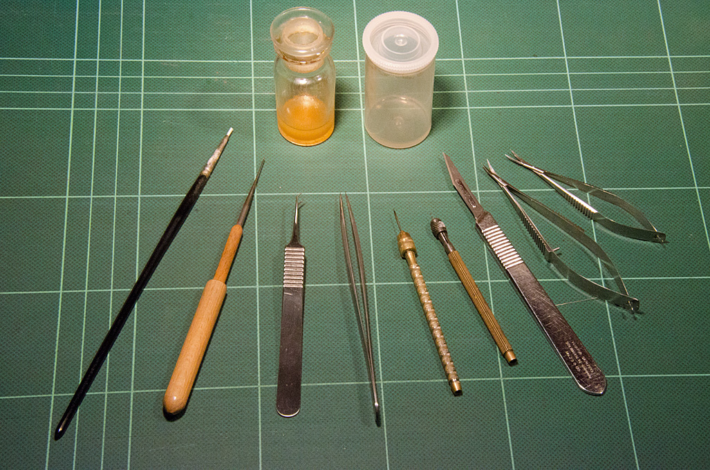
Tools used for
sailmaking
Hull
and mast after the application of a base coat of paint
Hull
painted and weathered
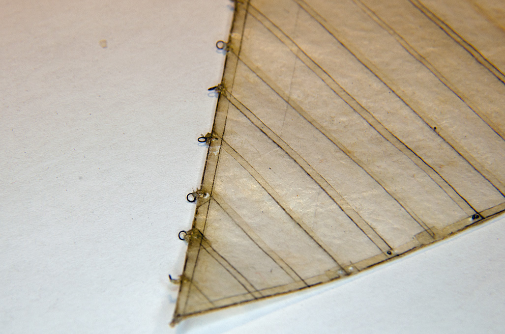
The sails were further completed by adding
cringles and eyelets. For the cringles the sail was punched with a
needle to simulate the eyelets. A piece of 8/0 yarn was threaded
through, twisted with itself and secured with a blob of lacquer.
The free ends were threaded cross-wise through the second eyelet
and secured with knots. The cringle was secured with a bit of
lacquer. For eyelets in the sail itself blobs of acrylic gel were
set on both sides and once dry punched with a needle. The foresail
runs on small iron hoops along the forestay. These were reproduced
by small rings of copper wire that were sewn to the cringles using
16/0 size yarn (Veevus). The sails
then were checked for any joints having come loose and more
wood-filler was applied if needed. Now the sails were ready for
painting. A terracotta colour ('terre' by Prince August Air) was
chosen as the base colour that was applied with an airbrush. Once
on the model some weathering and shading will add more plasticity.
- March 2013
Finally, the hull etc. were ready for the
application of a base coat of paint using the airbrush. A light
terracotta/flesh colour was used for the hull and an ochre ('bois'
by Prince August Air)
for the spars.
- April 2013
In order to create 'depth' of the surface and a wood-like
appearance, the hull and other parts were brush-painted with an
oak-coloured cellulose-based varnish. This proved to be not such a
good procedure as it is not possible to apply a second coat to
deepen the sheen, as the second coat tends to redesolve the first
coat. On a next project the varnish should be applied by airbrush.
The resulting uneven coating then was rubbed down cautiously with
fine steel wool and a glass eraser. This resulted in a suitably
'worn' look. This appearance was further enhanced by targeted
washing with acrylic burnt umber. The tarring of the underwater
body was simulated by a stronger wash of burnt umber. The rubbing
strake and the registration number board were painted in black,
the registration number was hand-drawn in white acrylic. Finally,
the hull was given a light coat in matt acrylic varnish (Winsor
& Newton), which resulted in just the right lustre.
In the next step all the iron work was given a coat in black
acrylic, followed by wash with a mixture of acrylic burnt and
'rouille metallique' (Prince
August Air), which gives it a sort of 'browned' appearance.
The metallic effect was further highlighted in places, where the
metal would have been worn bright by rubbing with a soft pencil
(6B).
As a last step grime and dryed salt spray were simulated by
rubbing-on black and white pastels with a brush and a cotton bud.
This procedure also gives the foredeck and the floorboards a
well-worn appearance. This procedure was applied to all individual
parts, not only the hull.
Hull
painted and weathered
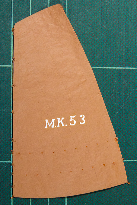
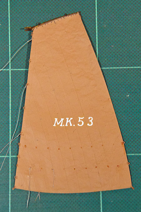
Main-sail
with reg. no.
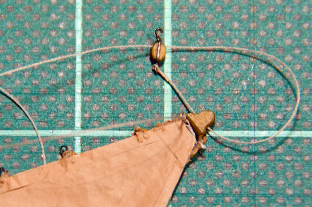
Reeving of the fore-stay
deadeye
The fore-stay deadeye
Hooked
-on fore-stay
Fore-sail with halliard
and sheet read to be set
Head
of the fore-sail
- July 2013
With the hull essentially complete, the
attention turned back to the sails and the rig. A job that
filled me with some apprehensions was painting the registration
number onto the botter’s main-sail. A bad job on this can spoil
the appearance of a whole model. Finding an easy way to produce
white lettering or other markings on a model would deserve a
modellers’ Nobel Prize. Any procedure I could think of requires
several, sometimes elaborate, steps. There are virtually no
printers that can print white. In the past there was one or the
other thermotransfer printer, but they seem to have disappeared
from the market. Owing to the fact that you really need heavy
pigments to arrive at good coverage, ink-jet printers are not
really a feasible technical route. Recently OKI came onto the
market with a laser printer that uses white, yellow, cyan and
magenta toners: http://www.okidata.com/procolor/711wt.
I don’t know anyone who has one already and for that price, I
would rather buy some other machinery. Printing on white decal
sheet is also not really a practical option, as you will never
match the background colour, at least not with the murky
terracotta I used for the sails. Then I thought about
stencelling. This would mean to etch a stencil first – too much
work for just two markings. Technically speaking, a good option
would be tampon printing. This is routinely used e.g. to apply
the lettering on model railway rolling stock. Again, you need to
etch a cliché first. For one offs, you could use a drill press
as transfer press. You would also need to find some chunk of
silicone rubber to make the tampon. All these options are too
involved, though I will be watching this laser printing thing.
Some day they may come out with a consumer version of it. So, in the end I
resorted to hand-painting. I took out my old lettering
stencils that hadn’t been used for decades and marked the
lettering on the sail. I then used a short-haired 5/0 brush
and white airbrushing acrylic paint. I had also experimented
with a pen, but the brush allowed more control on the somewhat
uneven surface of the sail. I painted the main strokes of the
letters/numbers and then added the serifs. They will have
rounded corners, but the lettering was touched up with the
base colour of the sail to get sharp outside corners. Finally
the sheen was equalized with a light touch of matt acrylic
varnish.
- August 2013
Once mast had been stepped the rigging of the model commenced.
The forestay of a botter is a particularity, as it is formed
from an wrought iron rod with eyes forged into its ends, rather
than being made form steel wire. The fore-stay of the botter is
hooked into an eye-bolt of the mast. This was truely reproduced.
There were various
methods of rigging the fore-stay of a botter in use up to the
end of the 19th century. I chose the somewhat old-fashioned
method with a dead-eye. The lanyard is a rope made on my own
rope-walk: three strands of Veevus fly-tying thread 16/0 in
golden brown. The colour was chosen because the lanyard would
have been tarred. I wanted to put a real wall-knot onto the
end, but the fly-tying thread works almost like wire and is
well nigh impossible to splice.
The dead-eye was set
up with the helpf of a small tripod.
On the prototype one would install, of course,
the fore-stay first. The fore-sail would be attached with its iron
hanks. In this case, however, the hoops have already been sewn
onto the sail, a work that would have been virtually impossible to
do in situ. Therefore, the fore-stay has to be installed
with the fore-sail attached to it. Form a modelling point of view
sailships of the late 19th / early 20th century are quite
difficult to rig. In previous periods ropes were often either
spliced directly into eye-bolts or sewn on, which both are quite
easy to reproduce in a model even at small scales. In later times,
to the contrary, shackles and hooks became ubiquitous. It made the
rigging and repair easier, but making shackles or hooks of 0.5 mm
or 1 mm length is quite impossible (the smallest shackles I
managed to make are about 2.5 mm long).
Clew of
the fore-sail
Fore-stay
made from a 'rod'
Setting
draping the fore-sail in half-set state
Rigging the fore-sail
sheet
Fore-sail head
- Autumn 2013
Now the rigging begins in earnest. As different sizes of rope are
needed for the various parts of the rigging, they are made on my ropewalk as the
rigging progresses.
In a first step the various blocks, namely the
sheep’s head-block for the fore-sail halliard had to be hooked
into the bolt-rope and a single sheet-block with second eye had to
spliced to the clew of the fore-sail. The halliard is an
interesting item, as it also serves as a down-haul, i.e. it sort
of endless its ‚free’ end is spliced around aone of the hooks of
the sheep’s head-block. In real life the halliard is a pointed
rope, meaning it becomes thinner at the ‚free’ end. However,
this cannot be reproduced seriously at the 1/90 scale.The sheet is also lead in
an interesting way. It is lead like a gun-tackle, but the second
single block inboard is missing. Instead, the sheet is lead
around the groove of a half-cleat on which it is also belayed.VAN BEYLEN
(1985) describes alternatives for the arrangement of the
fore-sail sheet, some of them lead like a gun-tackle, but with
one or even both single blocks missing. He does not explain the
rational for the absence of the blocks. The increased friction
would be of advantage when holding the sheet in strong wind, but
would make it more difficult to haul it in.
The mainsail was sewn onto to the port side of
the gaff. On those Dutch craft the lace-line runs through a
grommet of the head of the sail, then straight through a hole
drilled into the gaff with a pear-shaped cross-section, runs along
the starbord-side, returns throught the next hole and grommet,
continues along the port side of the sail to the grommet, etc.
Into the grommets of the fore-leech of the sail the various
lacings were spliced. With these the sail eventually will be tied
to the mast. Often chafing of the lacing was reduced by a number
of parrels. However, I neither could find small enough beads (0.6
mm diameter with a hole drilled through), nor did I manage to
produce them myself. The parrels are optional anyway. In the end I
wound a length of copper-wire around a 0.6 mm drill and painted
this wire tube in wood colour after bending it into an S-shape to
fit around the mast. I also put the reef points on. These reef
through a grommet and are secured by a knot on both sides.
Rigging
tools
Main
sail with with reefing points etc.
Head
of the main sail
Running
rigging at the mast
Stern
with boom-sheet
Shaping of rope
coils
Working
stand
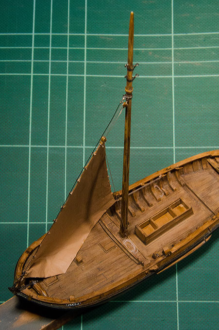
- November-Dcember 2013
The main sail was fitted out with the halliard
and the throat-halliard and then attached. The imagined szenario
is that the sails are set for drying. The shore of Volendam is
exposed to the East, so that the sails are slightly filled by a
light easterly breeze. The cold easterly breeze, that comes across
from Germany and the Baltic was a winterstorm a couple of days ago
and forced the botter to seek shelter in Volendam. The easterly
wind brought with it the frost that is responsible for the Marker
botter to be locked in the ice. The main boom has been topped a
bit to provide better clearance in the workspace underneath.
In the meantime various ropes of different size
were made from fly-tying thread. Then I also noticed that I forgot
to make that special block with a half-cleat that forms the lower
part of the main sheet tackle. This block was carved in the
classical way from a strip of Pertinax and fitted out with an
‚iron’ band etc.
The running rigging was attached by fake
eye-splices. On the prototype, all blocks are attached to
eye-bolts by hooks, which are secured by musings. The pictures do
not show this detail yet. Owing to this way of rigging, all
tackles could be prepared in advance and just hooked into their
respective eye-bolts. The throat-halliard is made up from a short
length of chain with an S-hook at its end. The S-hook is attached
to the eye in the bolt-rope. The throat-halliard is hauled taught
with a tackle that hooks into an eye-bolt in the mast. The S-hook
was made from a short length of wire that was flattenend and
provided with a hole in the middle for a chain-link.
The halliards etc. were belayed
prototype-fashion on half-cleats, which is rather difficult to do
at this small scale in comparison to the same process on normal
cleats. The rest was coiled up and stored at suitable places. I am
not sure how this was done really on the prototype, as the
half-cleat do not allow to suspend the coils in the usual way. The
rope made from fly-tying yarn is relatively stiff. However, with a
drop of flat varnish it can be persuaded to form more or less
orderly coils. Hanging coils have to be loaded while the varnish
dries in order to attain a natural shape.
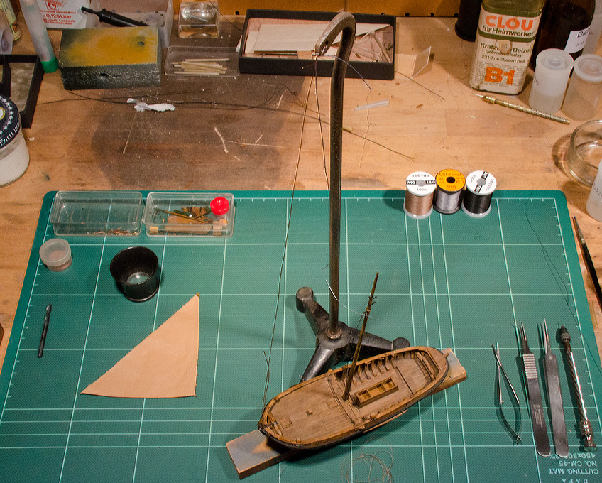
In order to facilitate the work on the rigging
the model was fixed on a small cast-iron stand. This stand can be
turned and pushed around on the work-table at one’s convenience,
yet is stable and safe. The actual rigging work is rather
difficult to photograph – one’s three hands are already busy and
there is no free hand for the camera.
The
fishing net on the botter model
Tanning
a net
Tool for making
(fish-)baskets
Weaving
fish-baskets[
The finished
fish-baskets
Different details to
go on board later
The botter is a fishing boat and a fishing
boat needs a net. But just this caused me some headache. In
accordance with the ‚story’ that is to be told in this scene, the
net will be shown hauled out up the mast for drying. This can be
seen on many old photographs. In these old photographs one also
notes the fineness of the yarn from which such nets were made.
There is not really any material that can convincingly represent a
fishing net in the 1:87 scale. The second best solution are the
finest ladies tights one can put one’s hand on. Unfortunately,
these don’t have quite the reddish-brown colour of a tanned
fishing net. In order to improve their resistance against the
elements, fishing nets were ‚tanned’, i.e. they were boiled in a
brew made from oak bark. An additional problem was, that I didn’t
have any detail information on what kind of nets a Botter would
have used in the winter fisheries on the Zuiderzee and how these
nets were constructed – VAN BEYLEN (1985)
just devotes half a page to the subject. There is a book by Pieter
Dorleijn, that apparently treats the subject in some detail, but I
found it too expensive to buy this book, just for the one net I
had to make. Therefore, I cheated a bit. As the tights didn’t have
quite the right colour, I somehow had to dye them, which turned
out rather difficult to do. First I pulled the tight over a
round-bellied bottle to open the meshes. A try with
mahagoni-coloured woood-stain failed, the material just didn’t
take up the stain. In the end I stabilised the tight with thinned
matt acrylic varnish applied with the airbrush. After cutting it
out, the ‚net’ was coloured using Sepia-ink, again applied with
the airbrush. The acrylic varnish allows the net to be draped in
an acceptably realistic way. The net then was glued with
solvent-based matt varnish onto the fore-deck. A few drops of this
fast-drying varnish also kept the draping in shape.
The lee-boards were brought on board too. They
are fastened with small round-headed nails. In reality the
lee-board would have been secured on the pin with a wedge in a
rectangular slot in its outboard end. As on the model this pin has
a diameter of only 0.4 mm, I gave up on the idea to recreated this
arrangement :) The lee-boards are raised by a simple tackle.
A block with a hole, fastened to the rail, redirects the pulling
force and acts as a stop. The lee-board halliard is belayed on the
aftermost half-cleat.
Also the various belaying pins found their
right places. The pins, turned from steel, were heated using a
hot-air soldering gun until they changed their colour to brown and
almost blue. This, in my opinion, looks quite like forged iron
that is slightly rusted.
- January 2014
A fishing boats needs some fish-baskets to store the sorted catch
in. I could not think a convincing method to fake such baskets and
dropped ideas of using fabric or wire mesh – there would always be
an unrealistic seam. If you have a closed or filled basket, you
may sculpt it from something and imprint the woven pattern, but
this does not work for empty ones. In the end, I decided to weave
real baskets, well almost. For this I needed a tool that would
give the basket its shape and allow me to handle it while weaving.
So I turned the little implement above from a piece of 5 mm
diameter aluminium and drilled a 2 mm hole all the way through it.
It will allow me make two baskets simultaneously. The material for
weaving is another issue. I would have like to use wire, but it
would have been difficult to actually weave with wire. So I used
some thin cotton thread for the stakes and fly-tying yarn for the
weave. First the ‚stakes’ were put into place by wind the thread
around the form tool in a continuous series of loops, passing the
return part through the middle of the center bore of the tool.
This then was woven out with the fly-tying yarn using a sewing
needle. The rim is a bit of a fake: normally the stakes would be
bent back one over each other to produce a stable and decorative
finishing. Here I made a double row of half-hitches with the
weave, i.e. the fly-tying thread. Once this was finished, the
‚basket’ was soaked in wood stain and then a few dabs of matt
varnish were applied to secure the weaving. The stakes with the
exception of two on each side then were cut off flush with the
rim. The remaining stakes were twisted into looped handles.
Finally the stakes were cut around the hole in the bottom of tool.
A bottom of the basket was faked by closing the hole with a good
drop of white glue. The baskets then were weathered using acrylics
paint (umbra). After looking at the museum-picture, I noticed that
I should paint onto the baskets the registration number of the
boat - so that catch can be identified at the fish auction.
One may notice on the above photograph that in the meantime also
the anchor, a grab, has been installed. Finding such small chain
is a challenge, but I got something suitable from a Bavarian model
railway supplier. While the links were nicely soldered and
blackend, they were actually round. Anchor chains, however, have
oval links. With a pair of pliers I slightly squashed the links
into an oval shape.
- Autumn 2014
Work on the botter model continued with a few pieces of
equipment as shown in VAN BEYLEN’s
book: a long and a short boat-hook, the the tiller, a
shovel-shaped bailer, a handspike for the spill, the pennant that
goes onto the mast-top ... and the ‚afwasbak’, a wooden box for
doing the washing-up, or sorting fish, together with a teapot and
couple of mugs in white emaille.
The teapot and the mugs were turned from brass. The spout and
handles were soldered or glued on, while the pieces where still
attached to the stock, as was done the painting. The pieces were
then parted-off back on the lathe. The teapot has a diameter of 2
mm !
Finally, all the equipment and the figurines described below were
put in their designated places. This concludes the work on the
model.
Scenic Setting -
The Story
Background
The kit is actually for a
waterline model, which somewhat limits the possibilities for
dioramic displays. It was originally envisaged to show the boat on
a slip such as that preserved in the Zuiderzeemuseum
in Enkhuizen, but being a waterline model this is unfortunately
not possible.
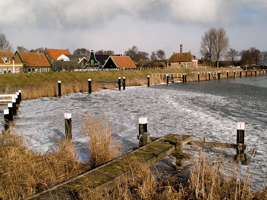
In developing a scenic setting
some sort of story-board is of great help. It sets down the
wheres, whys and hows, and thus helps to make the scene consistent
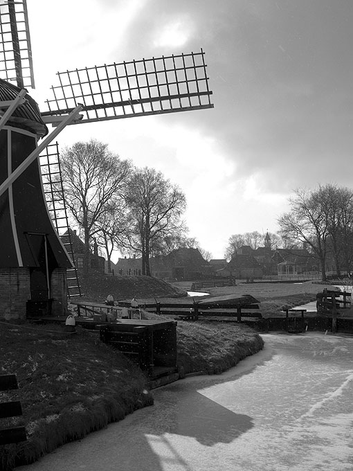
and logical. Having lived for several years in Noord-Holland, the
inspiration for the setting to be developed came from a winter
visit to the Zuiderzeemuseum
and a subsequent trip along the coast of the Isselmeer towards
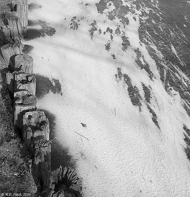
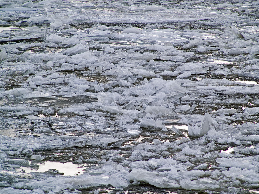
Volendam. Quite rare today, the canals and part of the Isselmeer
were frozen over. There was a thick accumulation of 'pankake' ice
floes around the coast, while the canals where frozen black, there
having been no snow. Appropriately the museum showed wintery
footage of locals ice-scating around frozen-in boats, taken in the
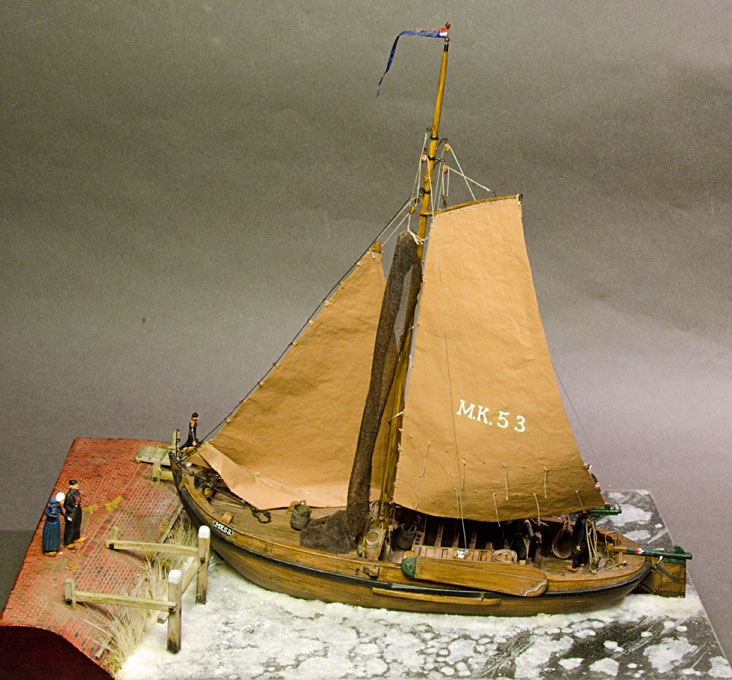
1930s in Volendam and Marken. Hence, the idea developed to show
exactly this scene: a botter from Marken trapped by the ice in the
harbour of Volendam; the sails were too stiff to be taken in and
are still half-set; the net is hoisted to dry, but would also be
frozen stiff; the skipper and his mate, dressed in the
charakteristic Marker dress with 'culots', while locals in the
Volendam dress - the men in baggy black trousers and tight black
jacket and waist-coat, the women with the well-known white lace
bonnet - scate past; there may be also a couple of kids on a
push-sleigh. The time would be around the turn of the 19th to the
20th century. This 'story' allows me to show both, the Volendam
and Marken costumes.
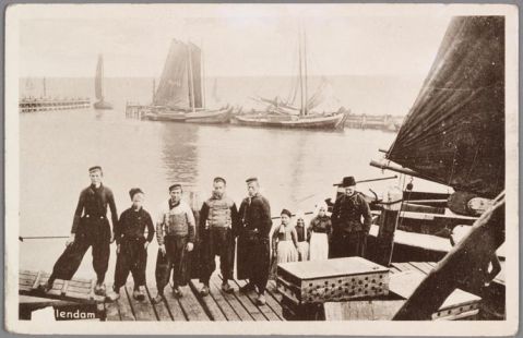
The area of Edam-Volendam and Marken has coined very much our
mental picture of the Netherlands, thanks to the numerous painters
who came to this area from the last quarter of the 19th century
onwards. They were attracted by the picturesque towns and villages
as well as the locals who still wore their traditional costumes.
Thus we came to think that the baggy trousers of Volendam and the
culots of Marken were the
Dutch men's costume. Similarly the women's dresses with a striped
apron and the peaked lace bonnet became synonymous for the Dutch women's
costume. They are picturesque, without question and somewhat
exotic when seen together with the large wooden clogs. So, some
fisherfolk in these costumes will add greatly to the atmosphere.
While the female costume from Volendam is rather pretty, I think,
to the contrary the traditional costumes from Marken are almost
ugly, particularly the headgear: the women used to wear the neck
and back of the head almost clean-shaven while long streaks of
hair protruded at their temples from underneath the bonnets ...
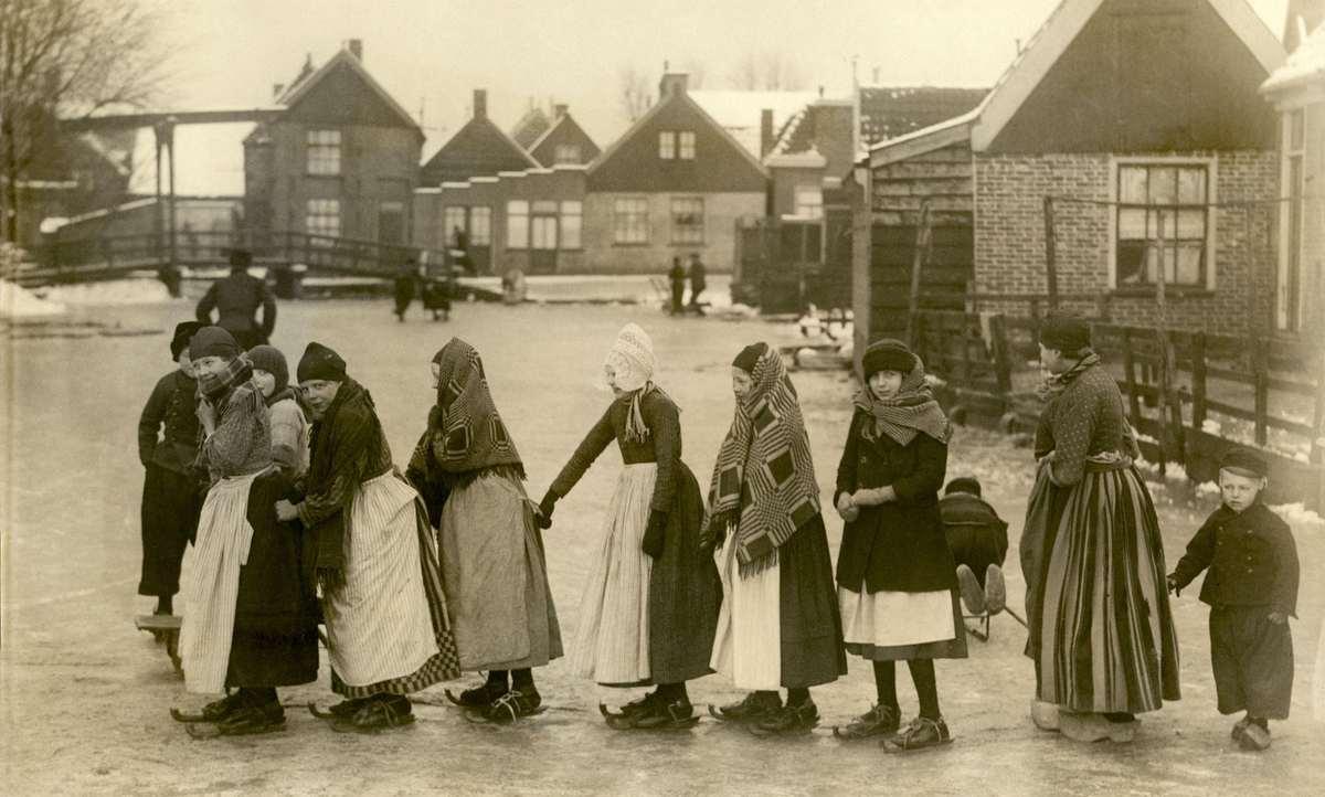
Photographs and paintings are
another source of inspiration for a dioramic setting and below I
provide the link to a number of them together with an
identification of the source, as the material might be
copyrighted:
Creating the scenery
and building the display case
The baseboard for the scenic setting is a piece
of blockboard cut to size in the DIY store. At a later stage it will
be protected by a (Plexi)glass display case with brass edges.
On the left side there will be a short stretch
of dike behind which Volendam is tugged away. The height is not
quite to scale, but I didn't want it to dominate the scenic
setting. The dike is framed by some left-overs of mitred laths and
filled-in with residues of balsa wood. The basis for the ice
surface will be a 2 mm Plexiglas sheet. I drilled a hole through
the board and the Plexiglas for the screw with which the botter
model will be fixed. Everything being glued together, I sanded the
four sides smooth and flush. The wood then was stained in mahagony
and varnished, as will be the frame of the display case. The
section of the dike was then covered in a thin layer of repair
plaster from a tube (I happen to have this and gave it a try,
rather than using plaster of Paris mixed with wallpaper glue).
Once hard, individual bricks were engraved with a needle held in a
pinvice. The whole surface was sealed with cellulose-based
woodfiller before painting with acrylics. The dike covered in
bricks was sprayed in English Red, while the water area was
sprayed in burnt umber and deepened with black. In order to create
a bit of variety, individual bricks were given a slight washing in
blue or burnt umber. The surface then was sealed with matt acrylic
varnish before a restrained weathering using pastels was applied.
Raw baseboard
Trial setting
Edges stained
Dike
modelled with plaster and
individual bricks engraved
Painted
and weathered
Trial setting
Jetty under
construction
With the Plexiglas sheet to simulate the ice in place the
positions for various piles that carry jetty were marked out.
The design of the jetty followed that seen on the historical
pictures above. Holes for inserting the piles were drilled
throught the Plexiglas into the wood. I cut some square strips
of soft wood on the table saw and from these 'piles' of the
appropriate length were chopped. The wood was roughend and
shaped using a rotary steel-wire brush in the hand-held drill.
Cross-pieces etc. were shaped from the same wood or match
sticks. The wood was stained in 'medium walnut', which gives it
a greenish-grayish weathered appearance. The pile-heads were
painted white (which gave them a better visibility in bad
weather). The effect of the seawater was reproduced by letting
the wood soak up some black stain from below. The piles were
further weathered with washes of white watercolour and pastels.
In real life the various members would have been fastened
together with iron bolts. Square washers prevented the bolt
heads and nuts from being pulled into the wood and splitting it.
The bolts and washers were imitated by taking simple brass nails
and milling a hexagonal head and a square on to them with a
set-up of an indexer
on the mill. The shaft was thinned down and parted off on the
lathe.
Brass nail
ready to milled
Milled bolt
head
Milling
machine set-up
Jetty
partly painted and weathered
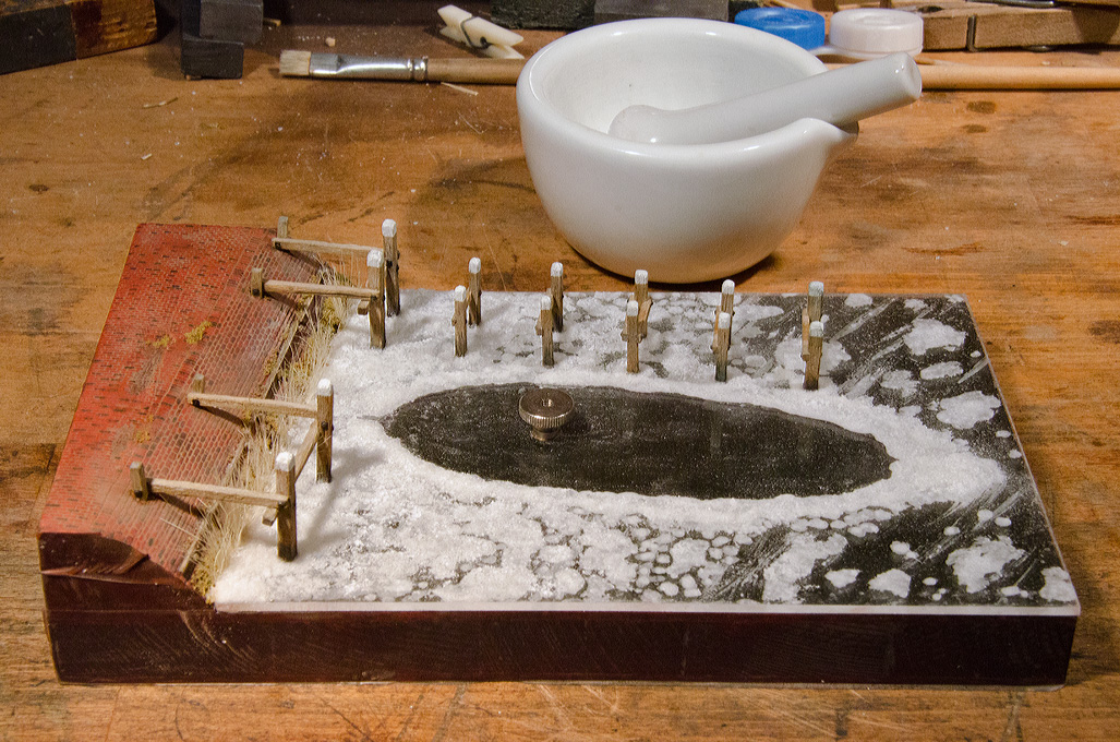
Volendam
harbour has been frozen over
The Plexiglas sheet that will become the ice surface was
stiffled with acrylic gel using a bristle brush. The next step
was a bit of an experiment: in the past I created drifting foam
and breaking waves using a sort of icing (no pun intended) made
from sugar and wallpaper glue. As we now have acrylic gel and
varnish, I tried out a mixture of sugar with these. The sugar in
France is rather coarse, so I ground it down in a mortar. The
sugar partially dissolves in the varnish and then
recrystallises. The viscosity can be adjusted by mixing sugar
and varnish in different ratios. It dries up milky-white. Using
this mixture, the ice floes were modelled in several steps.
Also, the piles were set into the ‚ice’ with this mixture. The
place for the botter was left free, but a low wall of ice will
surround it. This is meant to show the fruitless efforts of the
crew to keep the ice away from the wooden hull by breaking it up
with crowbars and axes. Actually, the real reason is that I did
not grind the bottom of the model perfectly flat and have to
hide a gap at bow and stern.
I also planted some reeds at the foot of the dyke and the
brick-work is beginning to be overgrown with grass. The grass,
though, suffered from the cold and has wilted to a yellow.
- July 2013 The construction of the glass case is inspired by the
design MCCAFFERY describes in his
book ‚Ships in Miniature’ of 1988. In the past I built display
cases from silicate glass. Silicate glass, however, is quite
heavy and fragile (particularly when moving house). So I decided
to give Plexiglas a try, though it is not as scratch resistant.
Besides I had sufficient supply of 3 mm sheets left over from
another project. They had resided in my stock of materials since
about 1980, but was as good as new. Lucky for me, the panels for
the case could be got from those sheets with just a few cuts. In
a domestic context, when you do not have a big table saw, sheets
of that thickness are best broken, rather than sawed. When
marked-out the sheets are scored with a ‚cutter’ knife. Per
milimeter of thickness it needs one go with the knife. It is
important to score right to the edge of the sheet, otherwise
corners may break out. The sheet is clamped down with the scored
line exactly at the table edge. Then, with a decided jerk, the
plate is broken off. A clean, straight edge that needs little or
no sanding before glueing is the result.
The individual parts were cut such that the front and back pane
abutt against the side panes. Since ordinary Plexiglas is much
more prone to scratching than silicate-glass, the protective
paper is being left on as long as possible. On the inside,
however, it would be difficult to remove, once the case has been
assembled. This was even more the case with the slightly oldish
sheets I am using. Therefore, the paper was completely removed
from the side that will face inward. On the outside a narrow
strip along the edges was removed to prevent the glue sticking
to it. The paper was only removed from the parts that were
assembled at that moment.
Plexiglas can be cemented together with a variety of glues,
including cyanoacrylates or those UV-hardening acrylates that
recently entered the DIY market. Epoxy resins, however, should
not be used, as their exothermic reaction can stress the
Plexiglas, which eventually will lead to fine cracks. If you can
produce a perfectly flat edge that is at a right angle to the
sheet, you can use a low viscosity cement. In most DIY
applications it is better to use a more gap filling
higher-viscosity cement.
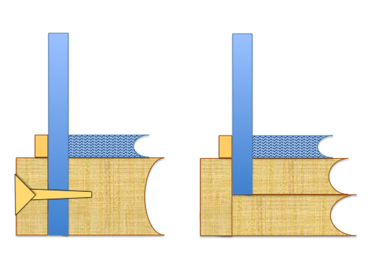
Design
for Plexiglas (left) and silicate glass (right)
case
Scoring
of the sheets before breaking (it
is covered in the brown protective paper)
The
broken edge
Cementing together the parts
of the glass case
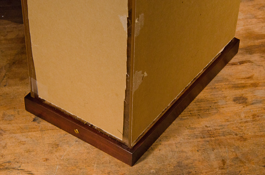
The
parts for the plinth
Waiting for the glue to set
The drilled and sanded
plinth
The stained and
varnished plinth
Plinth and glass case
joined
In order to achieve high quality bonds from both, the optical
and mechanical point of view, the best option is to use the
Plexiglas-manufacturer’s (Rhöm, now Evonik) own cements. I used
Acrifix 192, that is easy to obtain. Acrifix
192 is a light-hardening cement, essentially liquid
Plexiglas (more information on Plexiglas cements also at http://www.acrifix.com).
This means that the bond has almost the same optical and
mechanical properties as the sheet itself. According to the
manufacturer, Acrifix 192 has a shelf life of two years. The
stuff I bought apparently in 1998 and kept in different fridges
at various places around Europe since then worked without any
problems. Only the open time was a tad short, but this seems to
have been due to my two 100 W worklights. When I used only one
and turned it away from the case, I could work longer on the
bond. The parts were arranged
around the base plate. It would have been better to build the
case before starting the scenic display, but my impatience to
try out my ‚icing’ skills got the better of me. Now have to
work a bit more cautiously when cementing the parts together.
The four parts are held together temporarily by a gadget that
is normally used to fix picture frames and the likes during
glueing. In addition I used cellotape to keep the parts
together. In order to allow the application of cement, the
fixations are loosened a bit at the respective corner. The
cement is applied rather sparingly in order to avoid it
squirting out and damaging the surfaces of the Plexiglas
sheet. All four corners are cemented together one after the
other. It is possible to obtain
a perfect bond without any bubbles – with a bit of practice.
However, I wanted to be on the safe side and used a minimum of
cement, which may result in some bubbles. This is of no
consequence as the corners will be covered later by L-profiles
in brass anyway. The next step was to fit
a wooden plinth around the glass case. It was cut from 5 mm x
20 mm ramin-wood laths using a mitre-saw. The fit of the
mitres was perfected on a home-made disc-sander. After careful sanding on
the future outside, the parts were glued together using PVA
glue. The fixture for picture frames came handy here again.
When the glue had set, the top of the resulting frame was
sanded flat. Before that two holes were drilled through the
wood and the Plexiglas. They were countersunk for two brass
wood-screws with which the glass-case will be secured to the
baseboard. Actually, this
design is only possible with Plexiglas, as drilling
through silicate-glass would be a bit tricky to say the
least. In the past I used a design, where the glass
tightly fits into a groove of about 6 mm depth formed by
the baseboard and the frame and was not secured any
further. When this structural
work was completed, the plinth was treated with a mahagony
stain. After a light rubbing down with steel wool, it was
ready to be varnished, again in mahagony colour. A treatment
with wood filler and shellac in several rounds would have been
better, but with age one gets a bit lazy.
Creating the Staffage
In the scenic setting there will be several figures according the
assumed 'story'. In other words there will be the crew of the botter
whiling away there enforced stay in Volendam with some cleaning and
maintenance work on a sunny but wintery Saturday afternoon. On the
dyke a young couple with their baby have a stroll and on the ice a
younger man pushes his elderly grandmother on a sleigh. The starting
point was a set of unpainted figures from the Preiser-range.
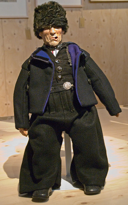
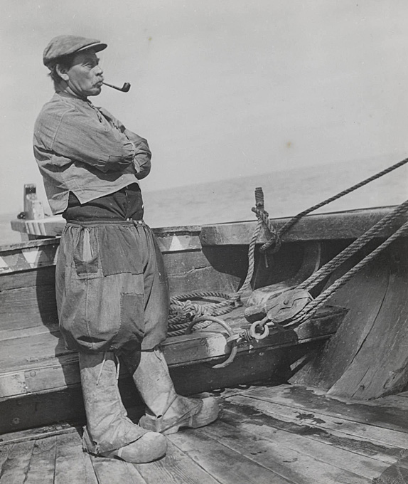
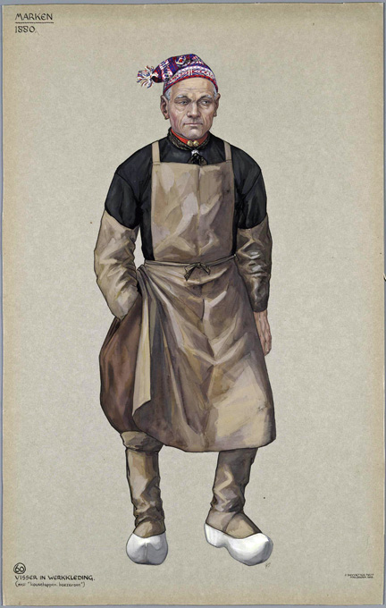
I selected suitable poses, to begin with for the fisherman and his
mate, who are both assumed to be from Marken. The dress of Marken
men is characterised by very baggy breeches- or culotte-like
trousers of dark (black, blue, brown) wool or of natural linen. The
lower legs are covered by dark woolen stockings. In the more clement
seasons a collarles heavy shirt is worn, sometimes also a crew-neck
sweater. In the more inclement seasons a jacket may be added, but
people at this time were hardy and these don't appear too often,
even on winter photographs. The head was protected by a round felt
hat, a cap like a forage-cap with a narrow shield or a knitted
'sock' cap. Around the neck a scarf was worn. For work and on
weekdays universally clogs were worn. The exact shape of clogs
around the Netherlands depends on in which village they were made.
There are many more details to the dresses, but this is not the
place for an ethnographic essay on Dutch folk costumes.
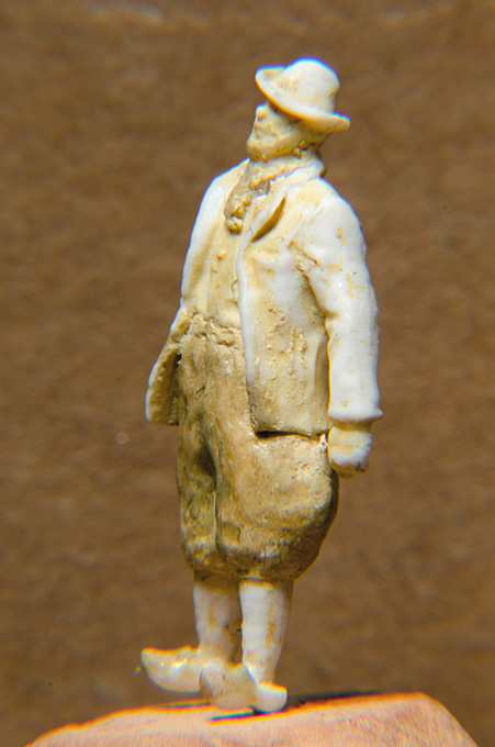
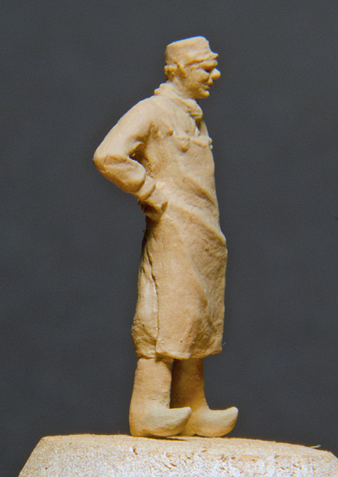
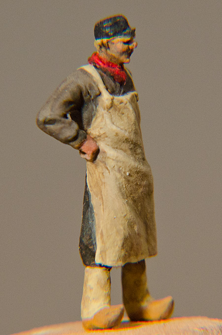
A range of photographs from the late 19th and
early 20th century provided inspirations for the conversions. The
Preiser figures were carved according to the needs of the dresses
or details were sculpted-on using putty. The changes become
obvious, when one compares the box art with the photographs of the
figures. A spray-painted base coat in a dark flesh colour make
imperfections glaringly obvious, when a photograph is taken. The
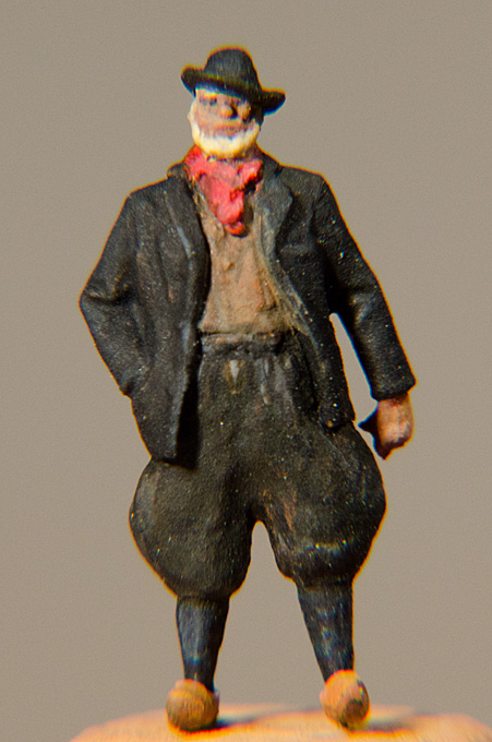
skipper will be clad largely dark, with the clogs having a light,
but worn wood-colour. Conversely, his mate will be at work,
cleaning some gear and, therefore, is dressed with a beige canvas
apron. He also put on his sea-boots, consisting of clogs with a
canvas bootlegs.
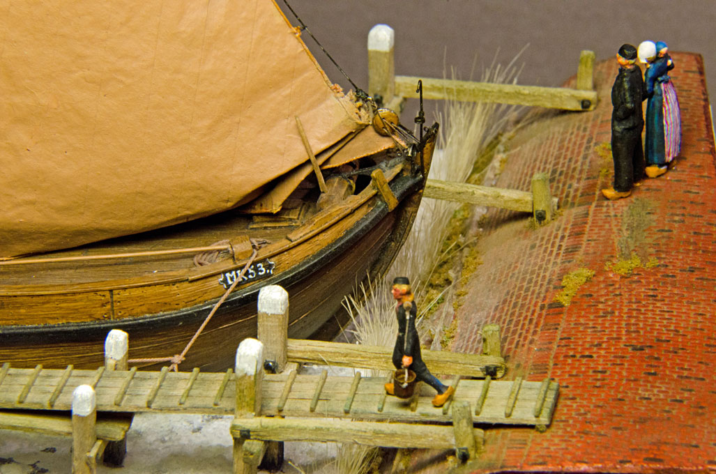
The botter-crew is completed by a boy, often a young relative, such
as a nephew, of the fisherman. The Preiser-set contained an old-time
uniform-clad bell-boy for a upmarket hotel. Fate turned him into a
rougher fisherman's boy who is carrying two buckets of freshwater on
joke from the village down the jetty to the boat - rather than the
hatbox of a fashionable lady. He is now wearing the baggy
'culottes', clogs and a shielded cap. The joke was carved from a
piece of phenolic resin-impregnated paper.
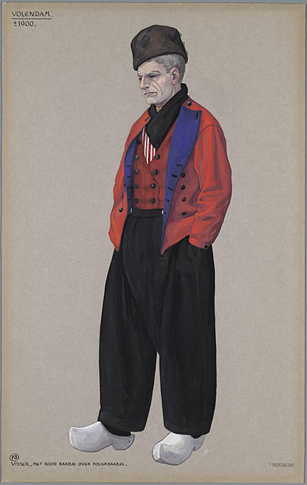
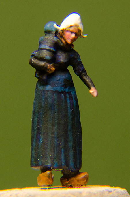
The traditional dress of the Volendam people is somewhat different
from that of Marken. The men wear long baggy black trousers, which
gives them a very distinctive silhouette. The upper body is covered
by a shirt and a tight-fitting jacket, which is often of some pale
red colour, but can also be black. In winter a sort of pea-jacket
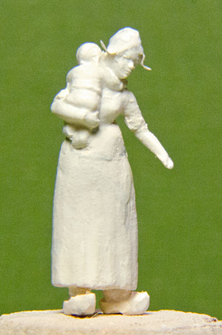
may be worn, which is black with blue lining. The women wear long
skirts over which a full-length apron is tied. The skirt is either
dark and then a white or striped apron is used, or the other way
around. The upper body is covered by a tight-fitting jacket under
which shirt is worn, that may be visible at the decolltée. According
to photographs and drawings there are many variations, particularly
for work-day dresses. The sleeves of the jacket for adult women were
only 3/4 length and pushed back to the elbows. In winter knitted
pull-on sleeves may be worn, put the fisherfolks were a hardy folk.
The most distinctive feature in the women's dress was the white lace
bonnet with starched and turned-up flaps at the sleeve. Both sexes
wore wooden clogs as everyday footwear, but leather slippers and
pantolettes were also used, particular to church on Sunday (BTW,
Volendam is an oddity, being a catholic village in a largely
protestant country).
Due to the fact that picturesque village and its equally picturesque
inhabitants drew many artists and tourists from the late 19th
onward, the Volendam costume became the best known and 'typical'
Dutch folk costume.
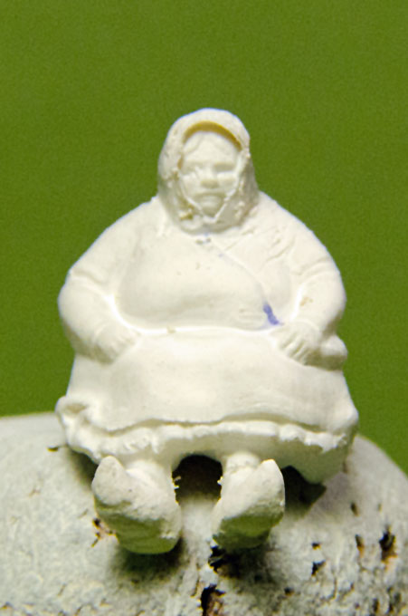
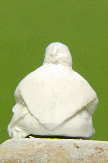
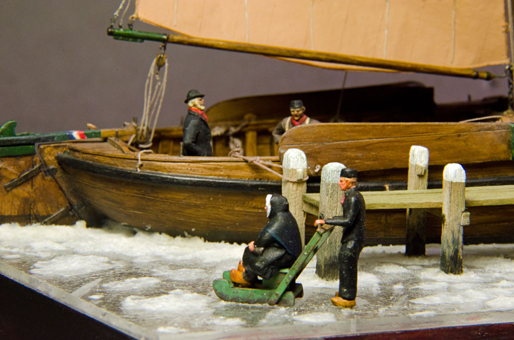
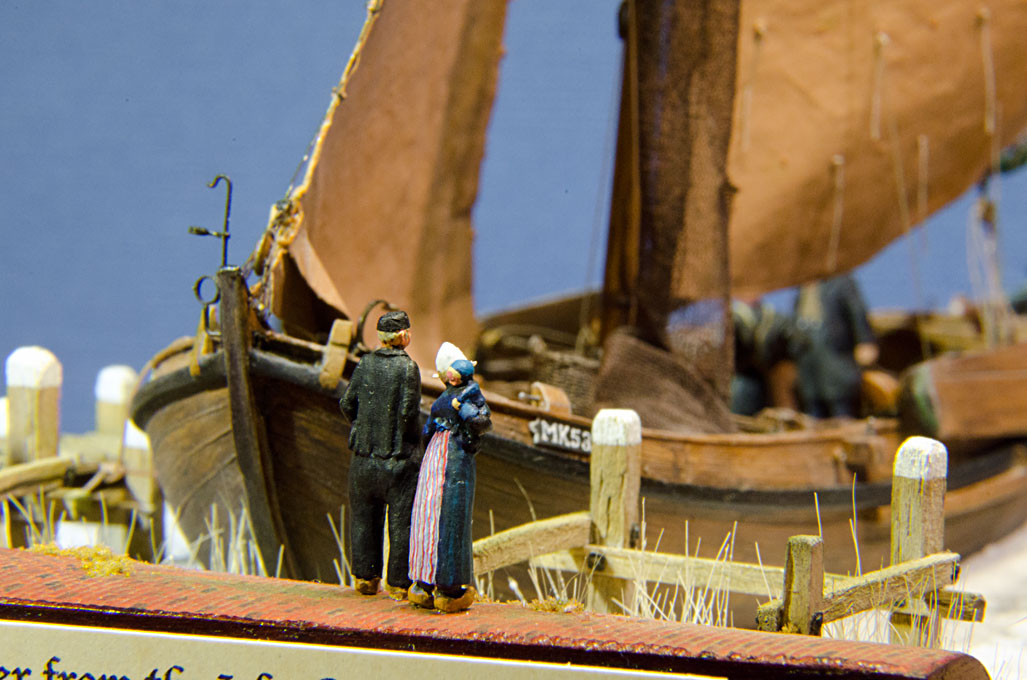
The first pair of Volendam folks is a young couple that has a stroll
on the dyke, while she is carrying their baby. The second pair will
be a younger man who pushes an elderly woman (his grandmother ?) on
a sleigh across the ice.
NOOTEBOOM, C. (~1925): De inlandsche scheepvaart.
Deel 11 van de gids in Het Volkenkundig Museum.- 79 p., Amsterdam
(Koninklijke Vereeniging ‘Koloniaal Instituut).
OSTROM, C. van (1988): Ronde en platbodems schepen en
jachten.- 144 p., Alkmaar (De Alk b.v.).
PEL, H. VAN (1956): How to tan nets, sails and
lines.- South Pacific Commission Quarterly Bulletin, 6(3):
33.
SOPERS,
P.J.V.M. (196?): Schepen die verdwijnen (bearbeitet von H.C.A. van
Kampen).- 162 p., Amsterdam (P.N. Van Kampen & Zon).
VOORBEIJTEL, W. (1943): Bechrijvende Catalogus der
Scheepsmodellen en Scheepsbouwkundige Tekeningen 1600-1900.- 191 p.
Amsterdam (Nederlandsch Scheepvartmuseum).


