last revised
21/12/07
A Micro Radius-Turning Tool
and Boring Head
Both, a
radius-turning tool
and a boring head essentially consist of a tool slide that rotates
around an axis perpendicular to that of the sliding movement,
allowing
the radius of swing of the cutting tool to be adjusted. Initially
I had
contemplated to adapt the geared dividing head and an existing
boring
head for the purpose of radius turning. However, it would be
rather
awkward to change the whole assembly during machining operations.
In
addition the overhang of the boring head would be considerable.
Hence I
decided to construct a tool from scratch. I was lazy, however, and
did
not make any drawings, just worked by eye.
Design
specifications: the
radius-turning tool should be capable to produce spheres with a
diameter as small as 0.3 mm, while the maximum capacity should
be
around
20 mm diameter. In addition, there may be a need to turn arcs
into
parts, which requires the rotating axis of the tool to be above
or
below the centre line of the lathe. To facilitate complex
machining
operations, it should be quickly interchangeable with ordinary
turning
tools. Hence, the radius-turning tool should be an accessory to
the
quick-change tool post. When I made the quick change tool post,
I made
a
few spare inserts with applications like this in mind.
|
|
|
|
|
|
|
|
|
|
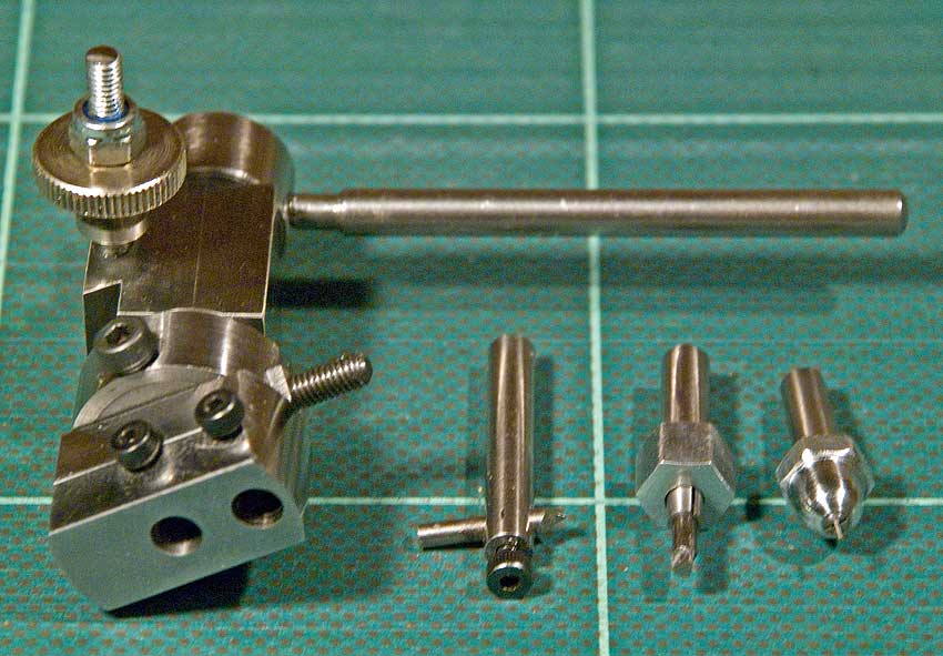
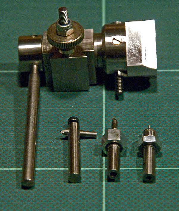
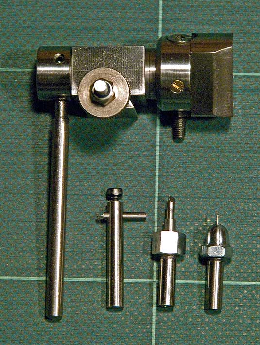
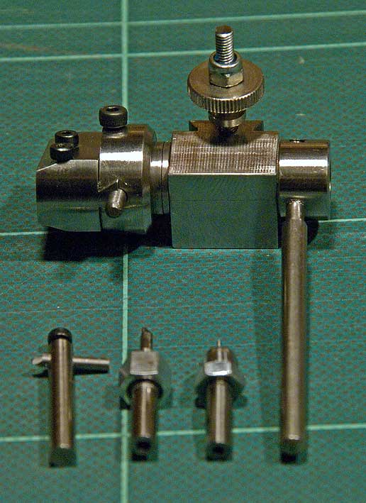
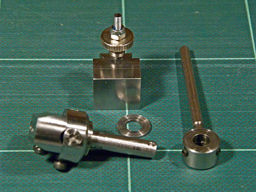
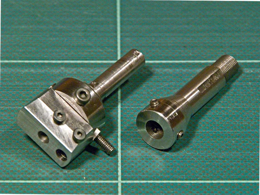
Different views
of the assembled radius turning
tool and the tool bit holders belonging
to it. |
Its
main
components
|
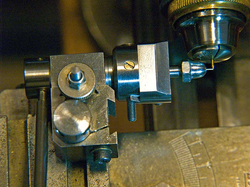
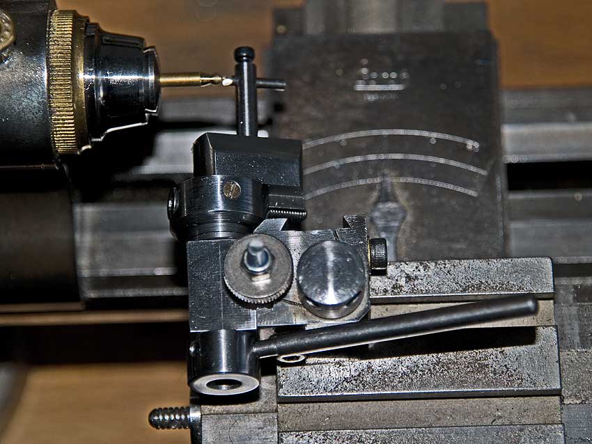
The tool on
the lathe -
before a cut.
|
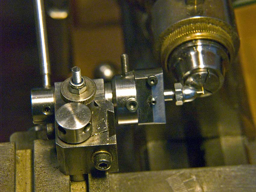
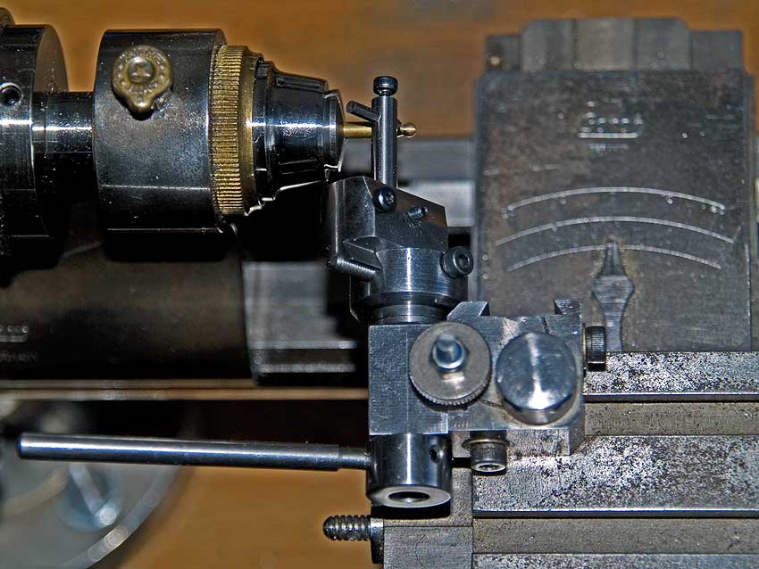
The tool on
the lathe -
after a cut. |
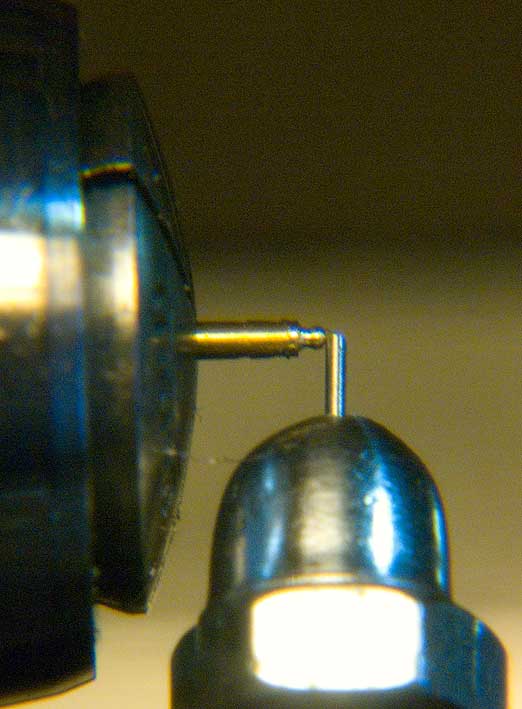
Close-up
view of
tool tip
|
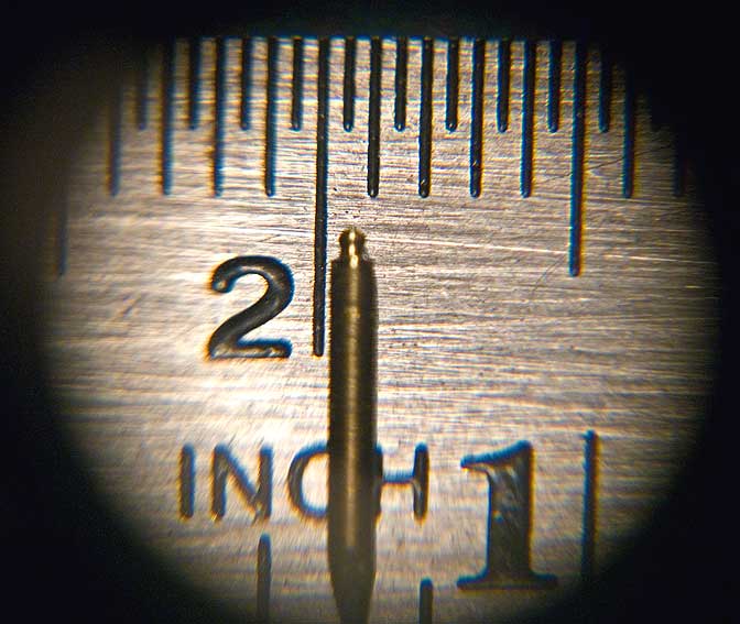
Viewed
through a loupe
(actually mm
not inches!) |
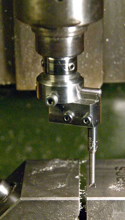
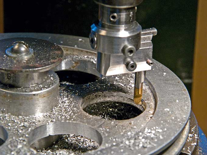
The tool
should also double
up as an ordinary, if rather small boring head. I have a set of
boring
tools with 4 mm shanks, so the head was configured for that
shank
diameter. While it would have been a good idea for a boring head
to
have a collet-type shank, I wanted to keep it interchangeable
between
the 6 mm and 8 mm lathes/mills. Also, producing a cone seat in
the
quick-change tool holder would have been rather more involved.
Therefore I settled on a straight 6 mm shaft, that can go either
into
an appropriate collet or into the end-mill holder for the mill.
The
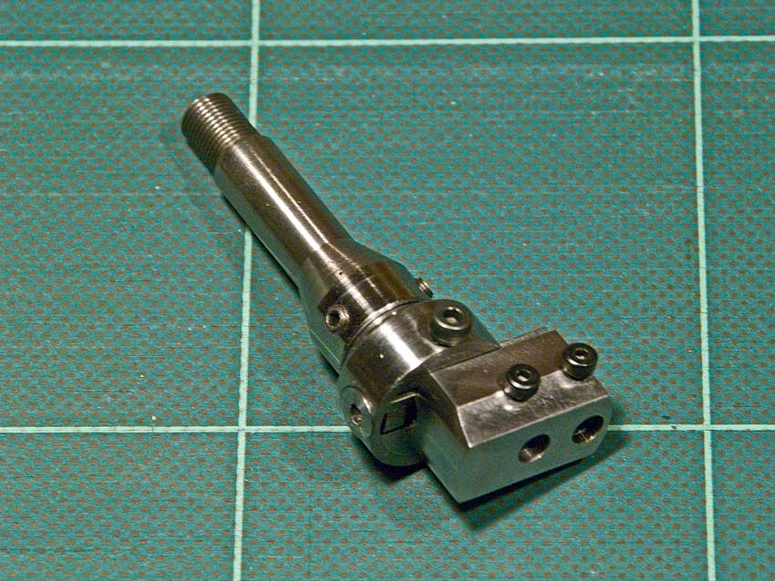
tool-holder block was
squared in the lathe to be drilled and reamed in situ. For the actual head
I used
material from the scrap box. A piece of 15 mm diameter round steel
was
faced off on the lathe and
then set up on the mill for milling the central dovetail slot with
a
miniature (6 mm) cutter that I had picked up at a flea-market many
years ago (never seen anything that small commercially).
Rather than providing a gib for the slide, with a circular saw I cut a
narrow slot next to the dovetail. This metal wedge is pressed
against
the slide with a single screw that also serves as a lock. I used
the
same arrangement on the large boring head and it works very well
as
movements are only small and in small increments. Before milling
the
dovetail, cross-hole was drilled through the body to receive the
movement screw, which is half in the dovetail and half in the
body.
This
hole was milled away half using a slot mill in preparation for
milling
the dovetail. The slide thus acts as a half-nut. The
movement screw is retained in place by a ring laid around the
head.
This ring of 20 mm OD was turned and bored on the lathe to a tight fit around
the body of tool. After
fitting and securing the ring with a sunk head screw, the
assembly was
returned to the lathe
and the shank turned down to the required 6 mm diameter.
|
|
|
|
|
|
|
|
|
Turning
a
'larger' ball
-
before the cut
|
Turning
a
'larger' ball
-
after the cut.
|
As boring-head
with end-mill
holder |
Tool mounted
in the end-mill holder |
With
boring
tool bit |
Ready to
work in the
vertical mill
|
Cleaning out
the relief
holes in a
pulley
|
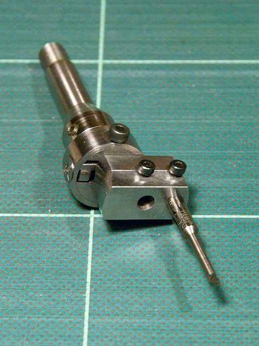
The tool
slide itself is
fashioned from a suitable piece of steel somewhat deeper then
required.
First the hole for the movement
screw was drilled close to the end and tapped M3. Then half of the tapped
hole was milled away and the dovetail was milled. Two sockets for
cutting
tools are
foreseen. The inner one, which would be crucial for turning very
small
balls, was drilled and bored while the provisionally assembled
head was
mounted in the lathe. This ensures concentricity of the tool
socket
with the shank. The second socket could not be machined in the
same
way, as the slide could not be moved into the right position.
Therefore, it had to be drilled and reamed on the milling
machine.
The head of the movement
screw (which is an Allen sunk head screw)
was engraved with five radial marks, indicating a movement of 0.1
mm,
based
on the 0.5 mm pitch of a M3 screw. It is thus easy to set it in
increments of 0.05 or even less, giving a corresponding diameter
change
twice this. I attempted to stamp the face of the screw with the
appropriate numbers, but failed to place the punch with necessary
precision in spite of using the punch guide described elsewhere on
this
site. A round slotted nut set with Loctite keeps the screw in
place.
Various
types of turning tool holders
where produced to suit the various envisaged tasks. Shown in the
pictures is
a more conventional one that is bored for a round tool bit
fashioned
from a broken twist drill. The other two holders are of a collet
type
to hold thin (down to 0.5 mm diameter) bits that cut at their
front
face. The idea is to cut with them a double radius whereby the
ball
merges into the stem via a S-curve. These collet-type holders
where
turned from a piece of 4 mm round steel. The front end received
a cone
and they were drilled and reamed to the desired toolbit
diameter. An M4
thread was cut on the lathe for the cup-nuts that were drilled
and
reamed to fit the cone on the holder.
Contact:
webmaster at wefalck
dot eu


